What this means is that this is a fascinating problem indeed, and worthy of our attention! First, it is clear that we must subdivide the surface of our planet into smaller pieces, since no single projection will handle all situations well. We also realize that the smaller the pieces, the less the distortion on each piece. It turns out that the Icosahedron is the regular polyhedron with the most faces. Furthermore, each face is a equilateral triangle. This last fact should prove useful for subdivision (or so I thought). An objective we must keep in mind while building a terrain renderer is tiling, if wish to conserve memory. Tiling triangles is rather awkward compared to rectangles, but still possible.
I present to you, the humble Icosahedron:
Please admire it's beauty, before we carry on with our discussion.
To reiterate, we are choosing a representation to accomplish two goals.
-Allow us to locate an object in space, and relative to the terrain
-Allow us to render the terrain at all locations on the globe. Ideally offering a good tiling method, and an easy way to subdivide a mesh.
The idea was rather simple. Each face of the Icosahedron (20 of them) would represent a coordinate space, each of these spaces would have a translation matrix to go from one to the other. We could then use each face's local euclidean coordinate system for locating objects.
For rendering, we could triangular tiles, and subdividing a equilateral triangle is a cinch for generating a mesh.
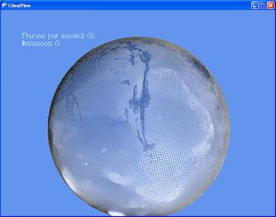
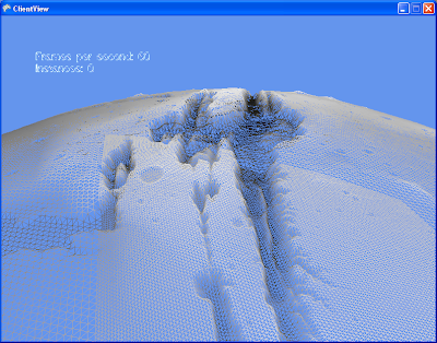
After much typing and compiling, I was able to present this result:


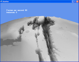
Presented here in wireframe for you to admire the mesh lattice. See how in the second shot we use dynamic tessellation to increase the mesh resolution closer to the camera.
Well, it turns out I made a very expensive mistake. While subdividing a equilateral triangle in euclidean space is a piece of cake, each triangle giving rise to 4 identical smaller triangles, this is not the case when projected on the surface of a sphere! What you get is 3 isosceles triangles and one equilateral triangle (in the center). Further subdivision just gives you an awful mess. One of my objectives when doing this was to re-use the subdivided meshes so I could instance them. While still possible with the clever use of stretching and vertex shaders, the trouble required starts to outweigh the advantages. In the image you see above, I resort to simply regenerating each mesh instance custom to the location it is in. My single-cpu machine complains, and I must resort to generating these meshes as background tasks to prevent stutters.
But worst of all is the absolute nightmare I had to go through to get those darn seams to dissapear. I had to replace many floating point calculations with equivalent ones that would give the exact same result when done on the adjacent tile. To give an example, instead of using a lerp function :
lerp(p0, p1, t) = p0 * (1-t) + p1 * t,
I used more of a weighing function like :
lerp(p1, p1, w0, w1) = (p0*w0 + p1*w1) / (w0 + w1)
Which, unlike the traditional lerp is symetric, therefore will give the same results regardless of the order of p0 and p1.

And here you see more seams. These are caused by the vertex shader sampling different pixel heights on both sides of the seams. Each of the 20 triangles has it's own texture map, so keeping the sampled value the same is another problem.
Then I had a better idea. Enter: Hardware-based azimuthal equidistant projection! (polar projection for short)
No comments:
Post a Comment