But first, I will introduce a regular rectangular mesh terrain rendering technique that underpins the approach. This is a continuation of the previous post "Icosahedron-based terrain renderer". So you'll want to start there if you want to get the full picture.
Let's start with a regular flat terrain renderer. Given a very large 2D heightfield, we sample a subtexture of fixed size around a given central (u,v) of our master texture. This gives us a smaller heightfield that we can run through a grid mesh, and we get a terrain patch. Now we take this system, and we render it 4 times, but sampling from a different mip level on the master texture. What we get is 4 concentric squares at different resolutions. To prevent fighting, the 3 outer meshes will have holes in the middle, leaving room for the smaller meshes. If we put the camera at center of all this, we get a natural LOD system!
Here's what the four concentric rings would look like:

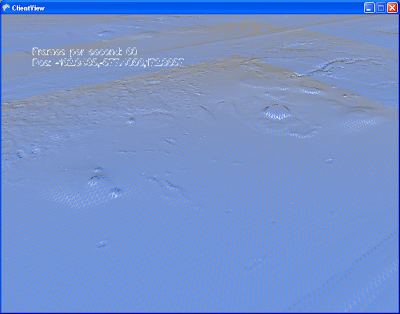
In these pictures, you see the "skirts" that were added to prevent seams from showing. There is a certain amount of overlap between these meshes even without the skirts. Both these techniques together fix the seams in most cases. The other cases arn't a problem as long as the camera is positioned within the highest resolution mesh. The end result looks like this, both in wireframe and shaded.


What's interesting about this technique, aside from it's simplicity, is that it opens up worlds of possibilities for how exactly to represent that initial 2D heightfield, and how to compose the final subtextures. You don't need to have only one huge texture as a source, and indeed you would not want to. You would most likely have a huge tiled virtual source texture. You could use the graphics card to compose together many patterns on the fly. You could use procedurally generated noise. If your texture composing becomes complex and costly, you can shave loads of cycles by not re-drawing the subtextures at every frame. If each subtexture is wrapped, all you have to re-draw is a small slither that came into view if the camera moved. Of course there are a few details I need to mention before we continue.
If you implement this too naively and you get a strange animation aliasing effect when you move your center(u,v) point. It's the the bilinear interpolation that is wobbling your heightfield. The solution to this is to only shift your (u,v) center by integer coordinates relative to your lowest LOD mesh. You make up the fraction bits by moving the whole assembly. These together produce a smooth, seamless animation as you move around on your terrain. (See the wireframe part of the video below to get a good idea)
In this particular example, it is also worth noting what I do with the normal maps. As source data, I have a heightfield, and a normal map. The heightfield is used by the vertex shader for dispacing the verts of the mesh, and the normal map is used by the pixel shader to determine the lighting. The nice thing here is that they don't have to be at the same resolution. In these pictures, I sample my normal maps at 4x the resolution of the heightfields. This gives the illusion of a 4x resolution displaced mesh.
Now, let's move on to the task at hand. Flat terrain engines are nice, but everyone and their dog built one, so now I will introduce the fun stuff. The non-linear functions.
Behold:

This is fundamentally the same technique as we've just discribed, but with a few parlor tricks applied on top. Proof:

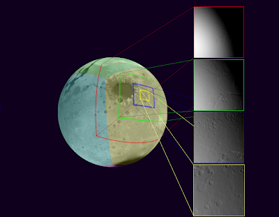
Here's how our texture generator works:

As a source representation for our heightfield, we chose the cube map. It has exhibits more pixel shear than the icosahedron in the previous post, but it's supported by the hardware, and the math is simple. As we increase the resolution of our master heightfield, we might not be able to rely on the built-in support for cube maps anymore, but the math is still simple, so it's a good choice nonetheless. The cube projection is entirely useable as-is if we were to create an adaptable mesh that is tied to it, but we end up with the same problems as we have with the icosahedron before. So we have to project from cube space to local space. Any Azymuthal projection would work. The projection method I chose is called Azimuthal equidistant. In a nutshell, every point on my flat local plane has the same distance and angle from the center as on the original sphere. This projection requires quite a bit of trigonometry in the shader. A better projection (calculation complexity-wise) would probably be the General Perspective Projection, with a suitably chosen perspective point. I'll have to try that one soon.
Another interesting thing about this approach is that the traditional normal map caluculations don't work. Tools typically calculate the normal(or gradient) in tangent space. In this case the tangent space is the surface of the sphere, so it needs to be re-calculated per-pixel. It is much more performant to simply store the normals in world space instead. I wrote a custom TextureProcessor for this for the XNA pipeline. It is _slow_, but it works well.
Here's a video in action. In the last section of the video, we switched to wireframe to show the details of the method. Unfortunately blogger seems to not like my high-resolution videos.
What's next: I have this wonderful adaptive resoltion mesh going on, but not high resulution data to throw at it! So the next step is to integrate some sort of tiling on the source so that I can load in some higher detail textures on demand.
No comments:
Post a Comment