Wednesday, February 20, 2013
Spunk and Moxie is live!
After over a year of hard work on evenings and weekends, Spunk and Moxie is now live on the app store!
Check it out:
Spunk and Moxie
Tuesday, June 17, 2008
Hardware-based sphere surface projection
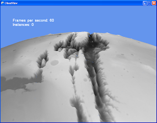
In this post I will introduce a method of rendering a spherical world in a way that uses the graphics hardware to do the best locally accurate projection possible at every location.
But first, I will introduce a regular rectangular mesh terrain rendering technique that underpins the approach. This is a continuation of the previous post "Icosahedron-based terrain renderer". So you'll want to start there if you want to get the full picture.
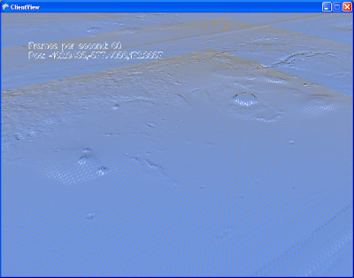
Let's start with a regular flat terrain renderer. Given a very large 2D heightfield, we sample a subtexture of fixed size around a given central (u,v) of our master texture. This gives us a smaller heightfield that we can run through a grid mesh, and we get a terrain patch. Now we take this system, and we render it 4 times, but sampling from a different mip level on the master texture. What we get is 4 concentric squares at different resolutions. To prevent fighting, the 3 outer meshes will have holes in the middle, leaving room for the smaller meshes. If we put the camera at center of all this, we get a natural LOD system!
Here's what the four concentric rings would look like:
In these pictures, you see the "skirts" that were added to prevent seams from showing. There is a certain amount of overlap between these meshes even without the skirts. Both these techniques together fix the seams in most cases. The other cases arn't a problem as long as the camera is positioned within the highest resolution mesh. The end result looks like this, both in wireframe and shaded.

What's interesting about this technique, aside from it's simplicity, is that it opens up worlds of possibilities for how exactly to represent that initial 2D heightfield, and how to compose the final subtextures. You don't need to have only one huge texture as a source, and indeed you would not want to. You would most likely have a huge tiled virtual source texture. You could use the graphics card to compose together many patterns on the fly. You could use procedurally generated noise. If your texture composing becomes complex and costly, you can shave loads of cycles by not re-drawing the subtextures at every frame. If each subtexture is wrapped, all you have to re-draw is a small slither that came into view if the camera moved. Of course there are a few details I need to mention before we continue.
If you implement this too naively and you get a strange animation aliasing effect when you move your center(u,v) point. It's the the bilinear interpolation that is wobbling your heightfield. The solution to this is to only shift your (u,v) center by integer coordinates relative to your lowest LOD mesh. You make up the fraction bits by moving the whole assembly. These together produce a smooth, seamless animation as you move around on your terrain. (See the wireframe part of the video below to get a good idea)
In this particular example, it is also worth noting what I do with the normal maps. As source data, I have a heightfield, and a normal map. The heightfield is used by the vertex shader for dispacing the verts of the mesh, and the normal map is used by the pixel shader to determine the lighting. The nice thing here is that they don't have to be at the same resolution. In these pictures, I sample my normal maps at 4x the resolution of the heightfields. This gives the illusion of a 4x resolution displaced mesh.
Now, let's move on to the task at hand. Flat terrain engines are nice, but everyone and their dog built one, so now I will introduce the fun stuff. The non-linear functions.
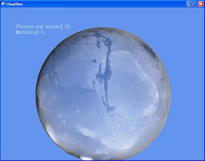
Behold:
This is fundamentally the same technique as we've just discribed, but with a few parlor tricks applied on top. Proof:

Here's how our texture generator works:
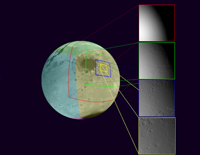
As a source representation for our heightfield, we chose the cube map. It has exhibits more pixel shear than the icosahedron in the previous post, but it's supported by the hardware, and the math is simple. As we increase the resolution of our master heightfield, we might not be able to rely on the built-in support for cube maps anymore, but the math is still simple, so it's a good choice nonetheless. The cube projection is entirely useable as-is if we were to create an adaptable mesh that is tied to it, but we end up with the same problems as we have with the icosahedron before. So we have to project from cube space to local space. Any Azymuthal projection would work. The projection method I chose is called Azimuthal equidistant. In a nutshell, every point on my flat local plane has the same distance and angle from the center as on the original sphere. This projection requires quite a bit of trigonometry in the shader. A better projection (calculation complexity-wise) would probably be the General Perspective Projection, with a suitably chosen perspective point. I'll have to try that one soon.
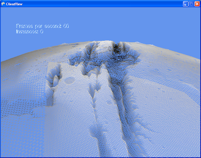
Another interesting thing about this approach is that the traditional normal map caluculations don't work. Tools typically calculate the normal(or gradient) in tangent space. In this case the tangent space is the surface of the sphere, so it needs to be re-calculated per-pixel. It is much more performant to simply store the normals in world space instead. I wrote a custom TextureProcessor for this for the XNA pipeline. It is _slow_, but it works well.
Here's a video in action. In the last section of the video, we switched to wireframe to show the details of the method. Unfortunately blogger seems to not like my high-resolution videos.
What's next: I have this wonderful adaptive resoltion mesh going on, but not high resulution data to throw at it! So the next step is to integrate some sort of tiling on the source so that I can load in some higher detail textures on demand.
But first, I will introduce a regular rectangular mesh terrain rendering technique that underpins the approach. This is a continuation of the previous post "Icosahedron-based terrain renderer". So you'll want to start there if you want to get the full picture.
Let's start with a regular flat terrain renderer. Given a very large 2D heightfield, we sample a subtexture of fixed size around a given central (u,v) of our master texture. This gives us a smaller heightfield that we can run through a grid mesh, and we get a terrain patch. Now we take this system, and we render it 4 times, but sampling from a different mip level on the master texture. What we get is 4 concentric squares at different resolutions. To prevent fighting, the 3 outer meshes will have holes in the middle, leaving room for the smaller meshes. If we put the camera at center of all this, we get a natural LOD system!
Here's what the four concentric rings would look like:

In these pictures, you see the "skirts" that were added to prevent seams from showing. There is a certain amount of overlap between these meshes even without the skirts. Both these techniques together fix the seams in most cases. The other cases arn't a problem as long as the camera is positioned within the highest resolution mesh. The end result looks like this, both in wireframe and shaded.


What's interesting about this technique, aside from it's simplicity, is that it opens up worlds of possibilities for how exactly to represent that initial 2D heightfield, and how to compose the final subtextures. You don't need to have only one huge texture as a source, and indeed you would not want to. You would most likely have a huge tiled virtual source texture. You could use the graphics card to compose together many patterns on the fly. You could use procedurally generated noise. If your texture composing becomes complex and costly, you can shave loads of cycles by not re-drawing the subtextures at every frame. If each subtexture is wrapped, all you have to re-draw is a small slither that came into view if the camera moved. Of course there are a few details I need to mention before we continue.
If you implement this too naively and you get a strange animation aliasing effect when you move your center(u,v) point. It's the the bilinear interpolation that is wobbling your heightfield. The solution to this is to only shift your (u,v) center by integer coordinates relative to your lowest LOD mesh. You make up the fraction bits by moving the whole assembly. These together produce a smooth, seamless animation as you move around on your terrain. (See the wireframe part of the video below to get a good idea)
In this particular example, it is also worth noting what I do with the normal maps. As source data, I have a heightfield, and a normal map. The heightfield is used by the vertex shader for dispacing the verts of the mesh, and the normal map is used by the pixel shader to determine the lighting. The nice thing here is that they don't have to be at the same resolution. In these pictures, I sample my normal maps at 4x the resolution of the heightfields. This gives the illusion of a 4x resolution displaced mesh.
Now, let's move on to the task at hand. Flat terrain engines are nice, but everyone and their dog built one, so now I will introduce the fun stuff. The non-linear functions.
Behold:

This is fundamentally the same technique as we've just discribed, but with a few parlor tricks applied on top. Proof:

Here's how our texture generator works:

As a source representation for our heightfield, we chose the cube map. It has exhibits more pixel shear than the icosahedron in the previous post, but it's supported by the hardware, and the math is simple. As we increase the resolution of our master heightfield, we might not be able to rely on the built-in support for cube maps anymore, but the math is still simple, so it's a good choice nonetheless. The cube projection is entirely useable as-is if we were to create an adaptable mesh that is tied to it, but we end up with the same problems as we have with the icosahedron before. So we have to project from cube space to local space. Any Azymuthal projection would work. The projection method I chose is called Azimuthal equidistant. In a nutshell, every point on my flat local plane has the same distance and angle from the center as on the original sphere. This projection requires quite a bit of trigonometry in the shader. A better projection (calculation complexity-wise) would probably be the General Perspective Projection, with a suitably chosen perspective point. I'll have to try that one soon.
Another interesting thing about this approach is that the traditional normal map caluculations don't work. Tools typically calculate the normal(or gradient) in tangent space. In this case the tangent space is the surface of the sphere, so it needs to be re-calculated per-pixel. It is much more performant to simply store the normals in world space instead. I wrote a custom TextureProcessor for this for the XNA pipeline. It is _slow_, but it works well.
Here's a video in action. In the last section of the video, we switched to wireframe to show the details of the method. Unfortunately blogger seems to not like my high-resolution videos.
What's next: I have this wonderful adaptive resoltion mesh going on, but not high resulution data to throw at it! So the next step is to integrate some sort of tiling on the source so that I can load in some higher detail textures on demand.
Icosahedron-based terrain renderer
Those of us who have tried to build terrain renderers that can represent a whole globe will be familiar with the Map Projection problem. It's a rather fascinating subject that I will defer to wikipedia . In a nutshell, it is simply impossible to project the surface of a sphere on a 2d plane without some sort of distortion, and/or spots that just don't work. As an example, the Aces Studio where I work recently shipped Flight Simulator X. It uses a equidistant cylindrical projection (WGS84) that most of you have no doubt already encountered when using Google maps at one point. The effect of this is that the square tiles in this space end up stretching pretty badly near the poles in real space. At the poles this gets so bad that they simply pinch to a point.
What this means is that this is a fascinating problem indeed, and worthy of our attention! First, it is clear that we must subdivide the surface of our planet into smaller pieces, since no single projection will handle all situations well. We also realize that the smaller the pieces, the less the distortion on each piece. It turns out that the Icosahedron is the regular polyhedron with the most faces. Furthermore, each face is a equilateral triangle. This last fact should prove useful for subdivision (or so I thought). An objective we must keep in mind while building a terrain renderer is tiling, if wish to conserve memory. Tiling triangles is rather awkward compared to rectangles, but still possible.
I present to you, the humble Icosahedron:

Please admire it's beauty, before we carry on with our discussion.
To reiterate, we are choosing a representation to accomplish two goals.
-Allow us to locate an object in space, and relative to the terrain
-Allow us to render the terrain at all locations on the globe. Ideally offering a good tiling method, and an easy way to subdivide a mesh.
The idea was rather simple. Each face of the Icosahedron (20 of them) would represent a coordinate space, each of these spaces would have a translation matrix to go from one to the other. We could then use each face's local euclidean coordinate system for locating objects.
For rendering, we could triangular tiles, and subdividing a equilateral triangle is a cinch for generating a mesh.
After much typing and compiling, I was able to present this result:
Presented here in wireframe for you to admire the mesh lattice. See how in the second shot we use dynamic tessellation to increase the mesh resolution closer to the camera.
Well, it turns out I made a very expensive mistake. While subdividing a equilateral triangle in euclidean space is a piece of cake, each triangle giving rise to 4 identical smaller triangles, this is not the case when projected on the surface of a sphere! What you get is 3 isosceles triangles and one equilateral triangle (in the center). Further subdivision just gives you an awful mess. One of my objectives when doing this was to re-use the subdivided meshes so I could instance them. While still possible with the clever use of stretching and vertex shaders, the trouble required starts to outweigh the advantages. In the image you see above, I resort to simply regenerating each mesh instance custom to the location it is in. My single-cpu machine complains, and I must resort to generating these meshes as background tasks to prevent stutters.
But worst of all is the absolute nightmare I had to go through to get those darn seams to dissapear. I had to replace many floating point calculations with equivalent ones that would give the exact same result when done on the adjacent tile. To give an example, instead of using a lerp function :
lerp(p0, p1, t) = p0 * (1-t) + p1 * t,
I used more of a weighing function like :
lerp(p1, p1, w0, w1) = (p0*w0 + p1*w1) / (w0 + w1)
Which, unlike the traditional lerp is symetric, therefore will give the same results regardless of the order of p0 and p1.
And here you see more seams. These are caused by the vertex shader sampling different pixel heights on both sides of the seams. Each of the 20 triangles has it's own texture map, so keeping the sampled value the same is another problem.
Then I had a better idea. Enter: Hardware-based azimuthal equidistant projection! (polar projection for short)
What this means is that this is a fascinating problem indeed, and worthy of our attention! First, it is clear that we must subdivide the surface of our planet into smaller pieces, since no single projection will handle all situations well. We also realize that the smaller the pieces, the less the distortion on each piece. It turns out that the Icosahedron is the regular polyhedron with the most faces. Furthermore, each face is a equilateral triangle. This last fact should prove useful for subdivision (or so I thought). An objective we must keep in mind while building a terrain renderer is tiling, if wish to conserve memory. Tiling triangles is rather awkward compared to rectangles, but still possible.
I present to you, the humble Icosahedron:

Please admire it's beauty, before we carry on with our discussion.
To reiterate, we are choosing a representation to accomplish two goals.
-Allow us to locate an object in space, and relative to the terrain
-Allow us to render the terrain at all locations on the globe. Ideally offering a good tiling method, and an easy way to subdivide a mesh.
The idea was rather simple. Each face of the Icosahedron (20 of them) would represent a coordinate space, each of these spaces would have a translation matrix to go from one to the other. We could then use each face's local euclidean coordinate system for locating objects.
For rendering, we could triangular tiles, and subdividing a equilateral triangle is a cinch for generating a mesh.
After much typing and compiling, I was able to present this result:


Presented here in wireframe for you to admire the mesh lattice. See how in the second shot we use dynamic tessellation to increase the mesh resolution closer to the camera.
Well, it turns out I made a very expensive mistake. While subdividing a equilateral triangle in euclidean space is a piece of cake, each triangle giving rise to 4 identical smaller triangles, this is not the case when projected on the surface of a sphere! What you get is 3 isosceles triangles and one equilateral triangle (in the center). Further subdivision just gives you an awful mess. One of my objectives when doing this was to re-use the subdivided meshes so I could instance them. While still possible with the clever use of stretching and vertex shaders, the trouble required starts to outweigh the advantages. In the image you see above, I resort to simply regenerating each mesh instance custom to the location it is in. My single-cpu machine complains, and I must resort to generating these meshes as background tasks to prevent stutters.
But worst of all is the absolute nightmare I had to go through to get those darn seams to dissapear. I had to replace many floating point calculations with equivalent ones that would give the exact same result when done on the adjacent tile. To give an example, instead of using a lerp function :
lerp(p0, p1, t) = p0 * (1-t) + p1 * t,
I used more of a weighing function like :
lerp(p1, p1, w0, w1) = (p0*w0 + p1*w1) / (w0 + w1)
Which, unlike the traditional lerp is symetric, therefore will give the same results regardless of the order of p0 and p1.

And here you see more seams. These are caused by the vertex shader sampling different pixel heights on both sides of the seams. Each of the 20 triangles has it's own texture map, so keeping the sampled value the same is another problem.
Then I had a better idea. Enter: Hardware-based azimuthal equidistant projection! (polar projection for short)
Sunday, June 15, 2008
Economy simulator
If you've ever played railroad tycoon, you would have noticed the nifty little supply/demand simulator they've got going on there. I don't know how deep their simulation goes, so I figured I'd try to make one and see if it works.
Eve online is another interesting experiment in market simulation. Although they cheat and use actual humans as their agents. They need _alot_ of them. Last time I checked, they had reached a peak of 40k concurrent users. If that's what you need to run a stable economy, that makes and awful lot of blue collar workers. I don't know about you, but when I play video games, I don't quite enjoy being _lower_ on the totem pole than how I am in real life.
So, what if we could build a full economic simulation out of AI agents, make it a stable and growing economy of say, 1 million units or so, and _then_ throw in some 40k human players in the mix? Assuming that the human players are smarter/better at making money than the AI agents, then that gives everyone the opportunity to control on average 25 other agents. Now _everyone_ can be the boss!
Back to reality. Who would have guessed that Adam Smith and Milton Friedman would be useful for game development. I tried to extract from their books the essence of a free market economy. It seems that the free market sounds alot like a multi-agent simulation.
We will setup the agent "Collective" as a graph. Each agent has a list of n neighbors, or friends, and only does business with them. This allows us to scale the simulation to 1 million without having to manage too many possible iterations. It also can help simulate the effect of "distance" and also trusted business partners. Everyone has their favorite place to shop, and producers have their favorite distributors. We can also bestow upon some lucky agents the ability to have more friends, making them "hubs" in the network. This would therefore give rise to market makers, distributors and merchants.
We'll make it a seller's market. The burden of setting the right sale price is on the producers. Producers put their goods on the market an arbitrary price. If it sells out, next round he will raise his price. If he is left with stock, next round he will lower his price.
The buyers will try to find the cheapest sale price for the good they wish to buy. They can only buy from their friends, so the search is bounded to a small set. Furthermore, we will incrementally sort the friend list by price, making this decision quite simple and quick.
Different agents will have different abilities. Each agent has a set of "business plans" available to execute. These business plans consist of "Actions". Actions are composed of a given "Technology", that operates on an instance of an "Asset". The Asset must provide the given type of "Capital" required by the Technology.
A given type of technology will have inputs (eg: labor), and outputs (eg: food, luxury goods). The technology specifies how many units of the inputs are required to produce a number of outputs. This way, different technologies can achieve similar goals, but with different efficiencies. As an example, consider farming. You can have BasicFarming that consumes 1 unit of labor, producing 1 unit of food, versus IrrigatedFarming, consuming 1 unit of water, 1 unit of labor, producing 1.5 units of food.
Capital is a property of an Asset, determining what one can do with that asset. For example, plains are suitable for growing food, and for raising livestock. Mountains would be suitable for Mining. Hills might be suitable for both, albeit at a lesser capacity. The idea here is to be able to simulate ownership of land, and investment in capital. You could buy an asset, containing unimproved forest. You could then cut down the trees (and sell the wood), leaving you with plains. You can now do farming on your plot of land. You could improve plains by doing irrigation works, increasing farming yields. You can improve a plot of land by building a factory, therefore making it now suitable for manufacturing.
We can't do everything at once, so let's get down to what I've done, and see how that goes.
In the simulation runs that we will soon see, There are two Technologies known by society. One is to produce food, the other is to produce art. Call it bread and games;) Producing food requires farmland, and producing art requires some sort of studio, park, or any other inspiring place.
For now, there exists only one Asset that we call "The Commons". Everyone can use it, and it allows everyone to produce food, and make art.
Simulation run 1: 10 agents, symmetric abilities.
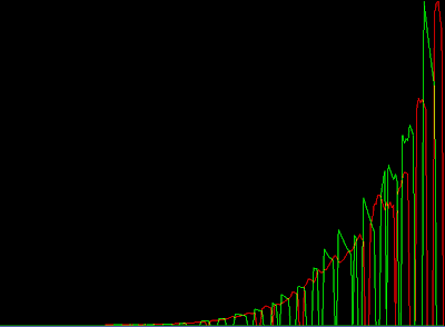
Price of goods as a function of time. Red: Food. Green: Luxury Goods (art)
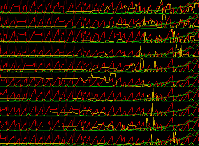
Stats per agent. Yellow bar: money. Bright Red/Green: Food/Art Quantity in stock. Dark Red/Green: Ask price.
What we're trying to get out of this simulation is self adjusting prices. We want the market to work. We expect the prices of various goods to stabilize according to supply and demand.
In this case, the market failed. Everyone can produce both Art and Food, so trading is not really necessary. The market can't quite find an equilibrium.
Simulation run 2: 10 agents, 1 luxury good expert, 9 food producers.


In simulation run 2, we have setup one agent that knows only how to make art, and the other 9 can make only food. We simulate division of labour.
Prices are stable, but they eventually converge towards zero. What seems to be happening here is that with 9 agents producing food, they compete with each other to sell food to the other agent. Prices free fall. The food agents can do nothing else but produce food, so they do so merrily. We have not yet introduced any required inputs to producing food aside from labor. Since we haven't programmed a minimum wage, and the agents do not know laziness, the low price of food is unbounded.
The artist gets rich. No two ways about that. The price of art increases, until all the agents have spent all their money. Without any money to buy the art, trading ceases, and the artist stockpiles his art, therefore he starts lowering his price.
This is obviously still not what we are looking for.
Simulation run 3: Asymmetric agents, Artist can only make food poorly, but is good at art. Farmers are good at food, but only adequate artists.
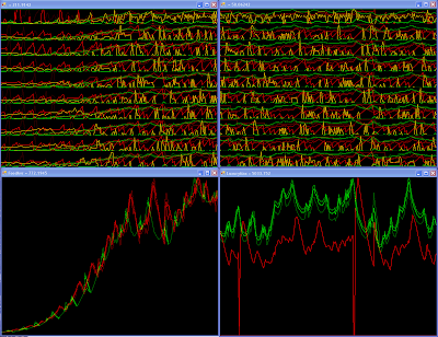
The panes on the left show the "bootup" state. The panes on the right show a snapshot of some frame later in the simulation. (click on the image to enlarge)
It seems we've finally found a stable system. The trading graph looks suspiciously like a stock market ticker ;) The vertical axis is always rescaled for maximum range, so it is not possible to tell on these pictures, but the price of Art is stable at roughly 9x the price of food. This is what we expected, with 9x the labor force specialized in food.
Soon we will tackle real estate purchase and capital investment. Stay tuned.
Monday, June 9, 2008
GJK in C#
While I was working for Microsoft, they were busy working on this kick-ass video game SDK for the hobbyists that you might have heard about : The XNA framework. Managed code is a pleasure to work with. This is just the type of thing to get me back into coding in my spare time. After attending GDC2006, I felt inspired to write my own implementation of the GJK collision detection algorithm, natively in C#.
For reference, I used Gino Van Den Bergen's paper on the subject (http://www.win.tue.nl/~gino/solid/jgt98convex.pdf). He was the presentor of the GDC talk. He has one of the most complete treatments i've seen of the nastiest problem that the algorithm has: numerical instability.
Christer Ericson's "Real time collision detection" book was also useful in explaining how this algorithm works.
Now I won't feel guilty of not explaining it here, and I'll just jump to some pictures!
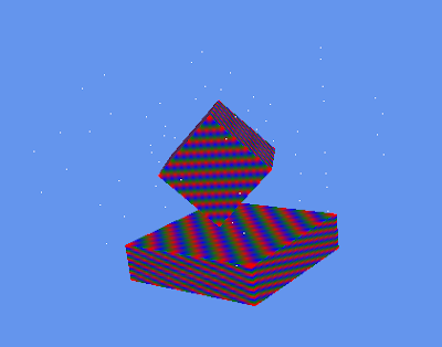
Here we see two boxes that are candidates for the intersection test. I'll direct your attention to the small white dots on the screen. These are the edges of the configuration space volume. It's a naive representation for debugging only, and all n^2 vectors are shown. The configuration space volume is defined by the convex hull around these points. The shape of this space varies as the relative orientation of the two objects changes.
The algorithm supports any convex shape that can be represented by a support function s(v). v is a direction vector, s(v) giving the farthest point on that convex in the direction v.
It just happens that it's easier to draw boxes, and debug them ;) So in theory, you could get any other sort of convex shape working here.
I managed to get this algorithm to work almost exclusively with floating point vectors. The idea is that these are the more compact, and therefore are more amenable to SIMD optimizations. The only place I couldn't skimp on was the determinant calculations in the closest point on simplex calculations.
With this setup, my current implementation of the algorithm is stable with face ratios of up to 1:100.
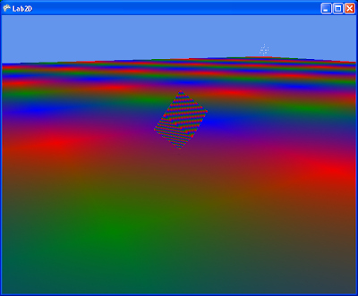
See the cluster of white points off in the distance? there're four of them near each end of the big surface box. This is fundamentally what causes instabilities in the GJK algorithm. The candidate simplex can be formed of a few points close together, and one way in the distance. This creates very long triangle surfaces that are difficult to solve because of high numerical imprecision.
College team project
My most "complete" project. Done in 2002-2003, as part of a school project. Normally the procedure was to get a company to sponsor a project, and work on what that company wanted. We had the great idea of asking one of my good professors, A. Alikacem to sponsor us instead, and work on a 3D game engine.
(watch this space)
(watch this space)
Past projects
Early college days... My English wasn't so good.
http://pages.infinit.net/quantum/ncoder/index.html
Dates from way back, 2001. Have fun!
http://pages.infinit.net/quantum/ncoder/index.html
Dates from way back, 2001. Have fun!
Subscribe to:
Comments (Atom)